
What is a schematic diagram? A schematic diagram is a simplified representation of an electrical circuit, system, or process using symbols and lines. These diagrams help visualize how different components connect and interact without showing the physical layout. Engineers, electricians, and hobbyists use schematic diagrams to design, troubleshoot, and understand complex systems. They are essential in fields like electronics, engineering, and even plumbing. By breaking down intricate systems into clear, understandable visuals, schematic diagrams make it easier to grasp how things work. Whether you're building a robot, fixing a car, or setting up home wiring, a schematic diagram is your go-to tool for clarity and precision.
What is a Schematic Diagram?
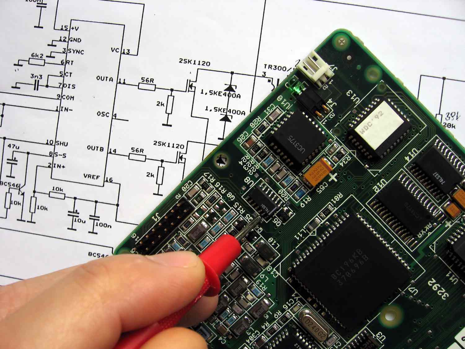
A schematic diagram is a representation of the elements of a system using abstract, graphic symbols rather than realistic pictures. These diagrams are used in various fields to simplify complex systems and make them easier to understand.
-
Simplifies Complex Systems: Schematic diagrams break down intricate systems into understandable parts, making it easier to grasp the overall structure.
-
Uses Symbols: Instead of realistic images, schematic diagrams use standardized symbols to represent different components.
-
Common in Engineering: Engineers frequently use schematic diagrams to design and troubleshoot electrical circuits.
-
Not to Scale: These diagrams are not drawn to scale, focusing more on functionality than physical dimensions.
-
Universal Language: The symbols used in schematic diagrams are universally recognized, allowing for easy communication across different languages and regions.
Types of Schematic Diagrams
Different fields use various types of schematic diagrams to represent their systems. Here are some common types:
-
Electrical Schematics: Used to represent electrical circuits, showing how components are connected.
-
Piping and Instrumentation Diagrams (P&ID): Used in the chemical and process industries to show the piping and related components of a physical process flow.
-
Architectural Schematics: Used in building design to represent the layout of electrical, plumbing, and HVAC systems.
-
Electronic Schematics: Used to represent electronic circuits, showing the connections between different electronic components.
-
Logic Diagrams: Used in computer science to represent logic gates and circuits.
Components of Schematic Diagrams
Understanding the basic components of schematic diagrams can help in reading and creating them.
-
Symbols: Each component in a schematic diagram is represented by a specific symbol.
-
Lines: Lines are used to represent connections between different components.
-
Labels: Labels provide additional information about the components and connections.
-
Nodes: Nodes are points where lines intersect, indicating a connection between components.
-
Reference Designators: These are unique identifiers assigned to each component in the diagram.
Importance of Schematic Diagrams
Schematic diagrams play a crucial role in various fields, offering several benefits.
-
Troubleshooting: They help in identifying and fixing issues within a system.
-
Design: Engineers and designers use schematic diagrams to plan and design new systems.
-
Documentation: Schematic diagrams serve as a record of the system's design and functionality.
-
Training: They are used as educational tools to teach students and new employees about complex systems.
-
Communication: Schematic diagrams facilitate clear communication between different teams and departments.
How to Read a Schematic Diagram
Reading a schematic diagram requires understanding the symbols and conventions used.
-
Identify Symbols: Familiarize yourself with the symbols used to represent different components.
-
Follow Connections: Trace the lines to see how components are connected.
-
Check Labels: Read the labels for additional information about the components and connections.
-
Understand the Flow: Determine the direction of flow or signal within the system.
-
Look for Reference Designators: Use reference designators to identify specific components.
Common Symbols in Schematic Diagrams
Knowing the common symbols used in schematic diagrams can make them easier to read.
-
Resistor: Represented by a zigzag line.
-
Capacitor: Represented by two parallel lines.
-
Inductor: Represented by a series of loops or a coiled line.
-
Diode: Represented by a triangle pointing to a line.
-
Transistor: Represented by a combination of lines and arrows.
Tips for Creating Schematic Diagrams
Creating a clear and accurate schematic diagram requires attention to detail and adherence to conventions.
-
Use Standard Symbols: Always use standardized symbols to ensure clarity and consistency.
-
Keep it Simple: Avoid unnecessary complexity by focusing on the essential components and connections.
-
Label Clearly: Provide clear and concise labels for all components and connections.
-
Organize Neatly: Arrange components in a logical and orderly manner.
-
Double-Check Connections: Verify that all connections are accurately represented.
-
Use Software Tools: Utilize schematic diagram software to create professional and precise diagrams.
-
Review and Revise: Regularly review and revise your schematic diagrams to ensure accuracy and clarity.
Final Thoughts on Schematic Diagrams
Schematic diagrams are more than just technical drawings. They’re essential tools for engineers, electricians, and hobbyists alike. These diagrams simplify complex systems, making it easier to understand and troubleshoot electrical circuits. Whether you’re designing a new gadget or fixing an old one, a clear schematic can save time and prevent mistakes.
Understanding symbols and connections in these diagrams is crucial. It’s like learning a new language that opens up a world of possibilities. From basic circuits to advanced systems, schematics provide a roadmap to innovation.
So next time you see a schematic diagram, remember its importance. It’s not just lines and symbols; it’s a blueprint for creativity and problem-solving. Dive into the world of schematics, and you’ll find a valuable skill that enhances your technical knowledge and practical abilities.
Was this page helpful?
Our commitment to delivering trustworthy and engaging content is at the heart of what we do. Each fact on our site is contributed by real users like you, bringing a wealth of diverse insights and information. To ensure the highest standards of accuracy and reliability, our dedicated editors meticulously review each submission. This process guarantees that the facts we share are not only fascinating but also credible. Trust in our commitment to quality and authenticity as you explore and learn with us.